3 Wires Universal Power Supply Module Circuit Diagram
It is necessary to make an universal device capable of charging all types of batteries i have and powering 5v electronics from this battery. Final words about the arduino power supply module:
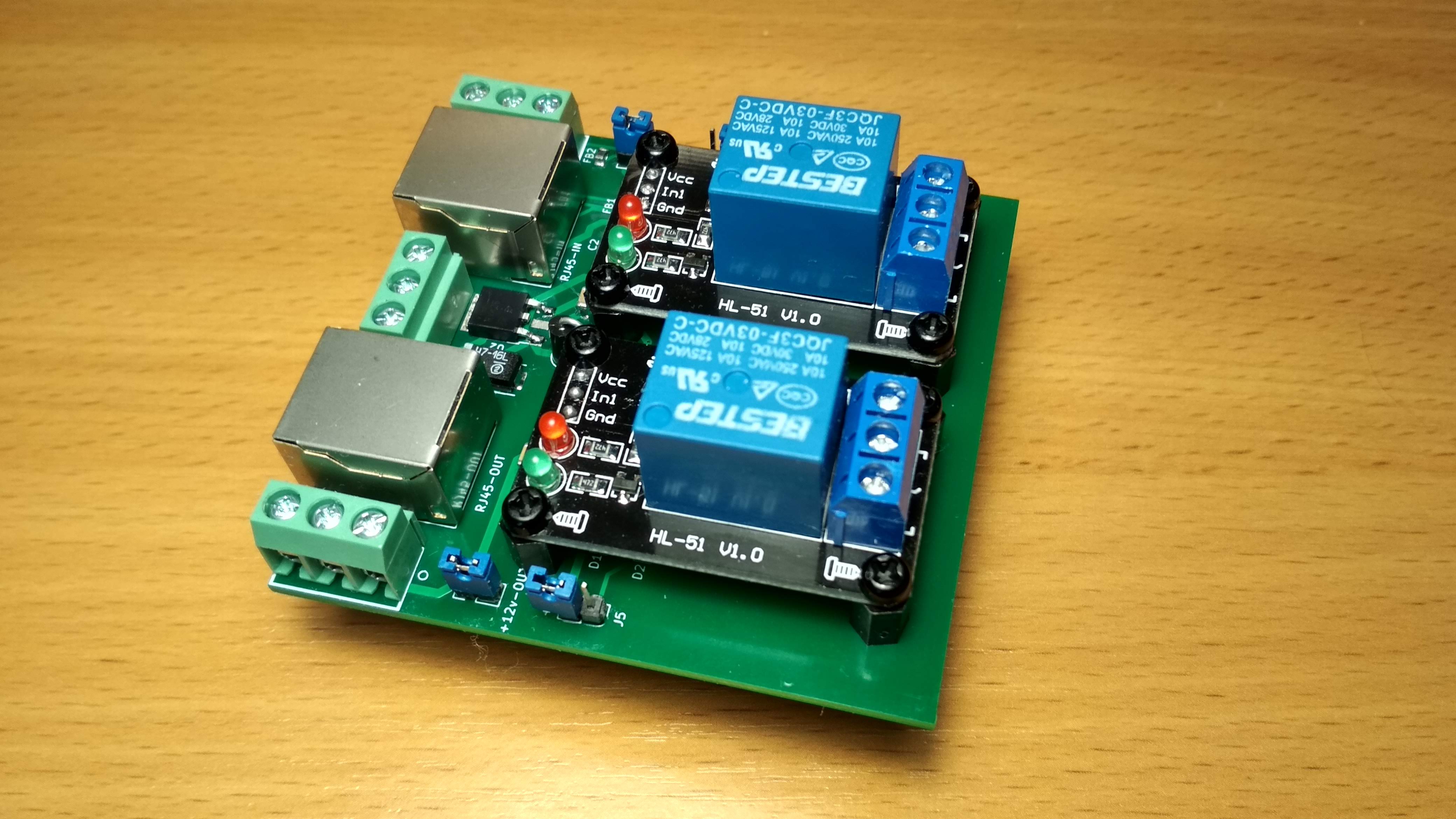
1wire relay/sensor, 2 channels ( DS2413P chip )
Ge fanuc support quickpanel cable diagrams.
3 wires universal power supply module circuit diagram. I needed to use a separate power supply for each of the tp4056 modules. One of such power is that used in a double door refrigerator. If you are swapping out a 480v magnet coil to supply one with 240v coil to meet a customer’s needs, you do not need
Universal power supply module 5v 24v youtube. When the output current is too high, the voltage across rs (manganese copper wire) rises, and the voltage at pin 3 of u1 exceeds the. 15 5 wires universal power supply module circuit diagramthe additional power transistor takes the load current of about.proton satria neo factory service manual 2006 2018 sho malaysia.
Electrical wiring diagram provides circuit diagrams showing the circuit connections. Use copper wire (75ºc min) only between disconnect switch and unit. Field power wiring ground see rating plate for volts & hertz disconnect per nec see note.
Currently, there is no product exhibited in universal power supply module. 1.0.1 power supply block diagram power supplies in recent times have greatly improved in reliability but,. Hope you find this guide useful to build your own 3.3v power supply circuit.
2004 corolla (ewd533u) 3 how to use this manual b this manual provides informat ion on the electrical circuits installed on vehicles by 3 wires universal power supply module circuit diagram. What i have done so far is to power with usb and connect lipo to points e and f.
Send an inquiry to this supplier * from: The principle diagram of a typical switching power supply (2)the block diagrams along with their description in a switching power supply are as follows: Overcurrent protection circuit or the short circuit protection circuit will work to stop the operation of the entire power supply circuit.
I wish i had designed this arduino power supply module a long time ago. The transformer voltage must be greater with 4v than dc stabilized voltage. A volt meter is connected to d and g and this gives me charging.
But did you check ebay. Universal power supply circuit diagram Input rectification input inrush current control filter protection converter feedback power factor correction circuit control output rectification output figure 1.4 block diagrams.
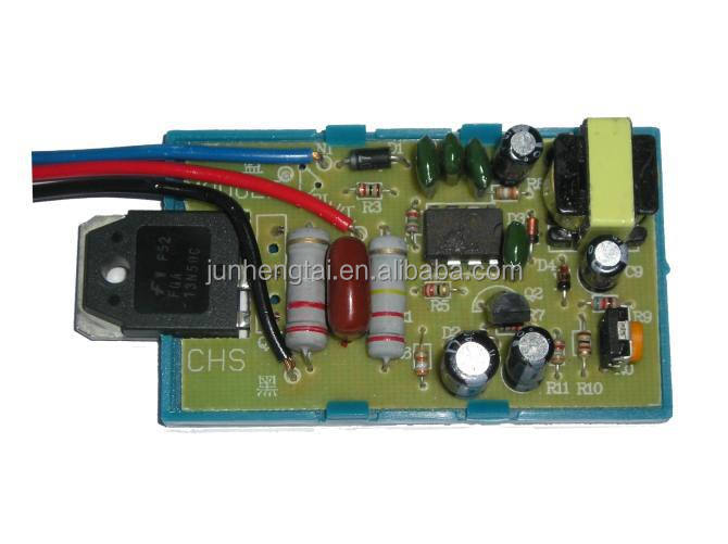
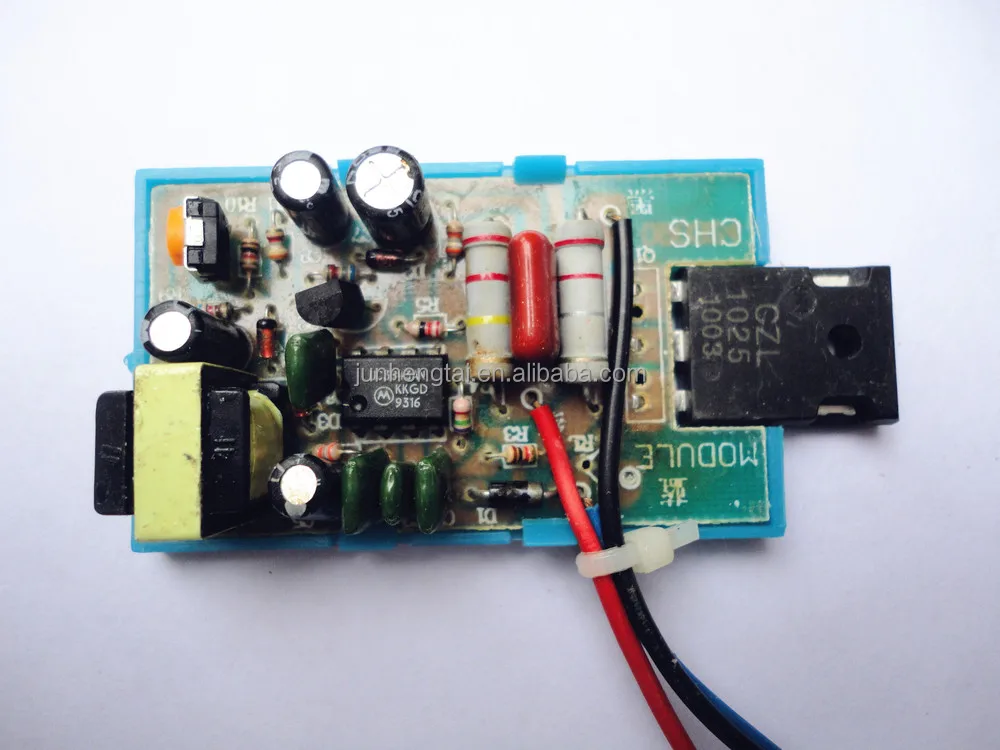
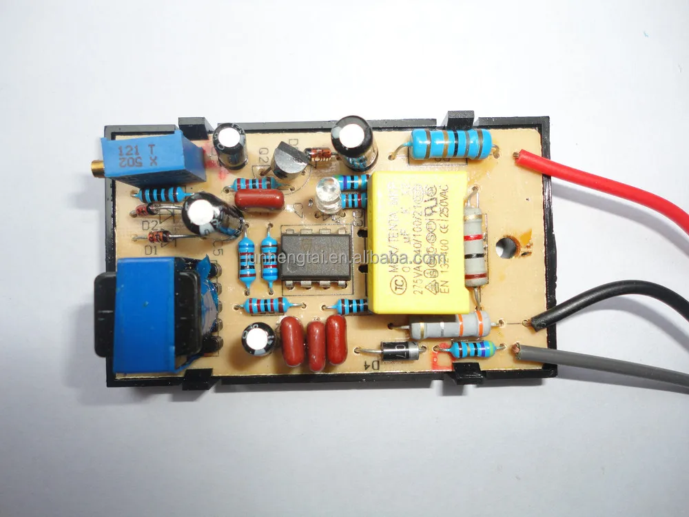
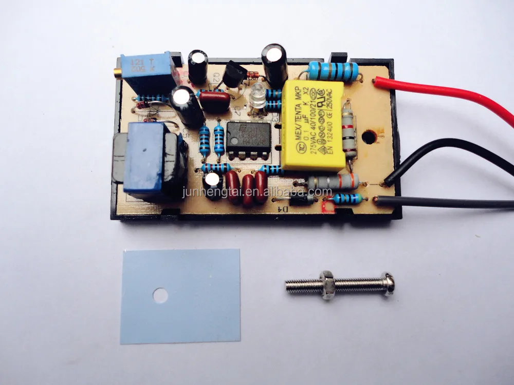
C1 is calculated for 1a/1000uf, so at 5a c1 must have 4700uf. To connect the module,neglect the green wire.connect the black wire to the negative terminal of the electrolytic capacitor (400v100uf).for the red wire do not connect to the positive of 400v100uf that's where some people get it wrong but instead as shown in the picture below connect. Describes power distribution from the power supply to various electrical loads.
3.3v = 1.25 ( 1 + r2 / 120 ) r2 = 196 ohms. Fixing the r2 value as nearest resistor element 200 ohms, this will give 3.3v as output from the above circuit. The cap 10uf tied to the voltage divider is meant to remove ripples from the output for a constant voltage level.
If any of the original wire, as supplied, must be replaced, use the same or equivalent type wire. Send an inquiry to this supplier. Typical wiring diagram line diagrams show circuits of the operation of the controller.
This is cable c below one wire connects to l1 and the other to l2 on the top switch. Motor operates at the power circuit voltage, in this case, 480v. Block diagram of switching power supply circuit.
Now i can easily distribute the 12v, 5v, 3.3 volts, and ground wires. Universal power supply module 5v 24v. After making this power supply module now i can easily power up different sensors and electronic breakout boards.
Power supplies module 01.pdf 2 e. Universal mobile power supply module for arduino. Module 3 switched mode power supplies 3 module 3.1 the buck converter the buck converter uses the energy stored in the inductor l, during the on periods of the switching transistor output to supply the load during the off periods.
The circuit operation depends on what is also sometimes called a flywheel circuit. To be wired in accordance with n.e.c. 400 watt 70 volt amplifier schematic amp pcb layout design.
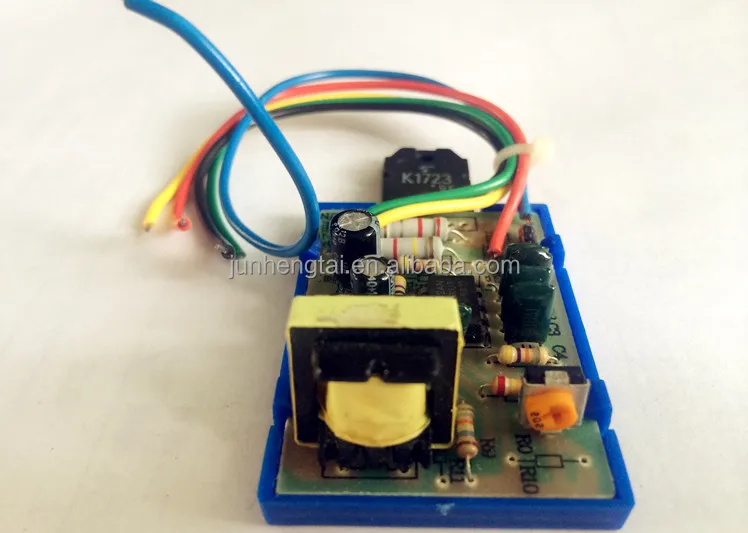
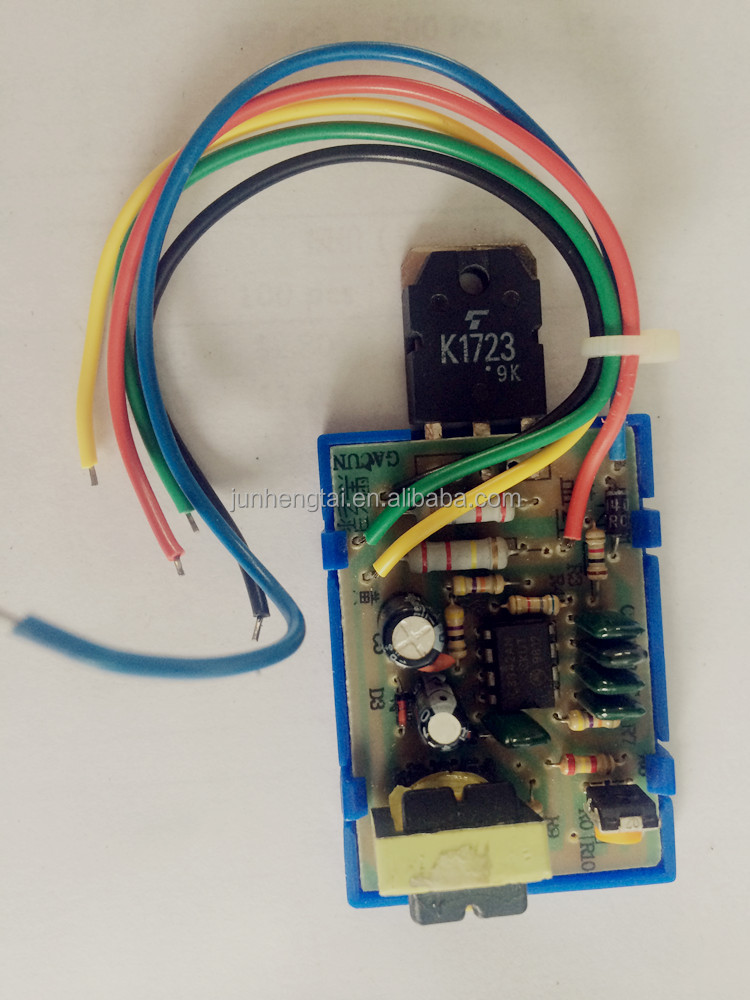
Power supply and power control circuit diagrams circuit. This module is of 3 wires,with the simplest conncetion and diagram circuit,. 5 wires universal power supply module circuit diagram 5 12 24 volt cctv camera dvr
The additional power transistor takes the load current of about 200ma. Fanuc a06b 6087 h145 power supply module btm industrial fanuc for power supply module wiring board motor parts Both, transistor and voltage stabilizer must be mounted on a heatsink.
Dual power supply circuit 3v 5v 6v 9v 12 15v lm317 lm337 Sac bus wire lengths versus number of doors and current loads using 14 awg wire 93 circuit compatibility matrix 94 paige wire tables 95 table of contents Supply and power control circuit diagrams circuit.
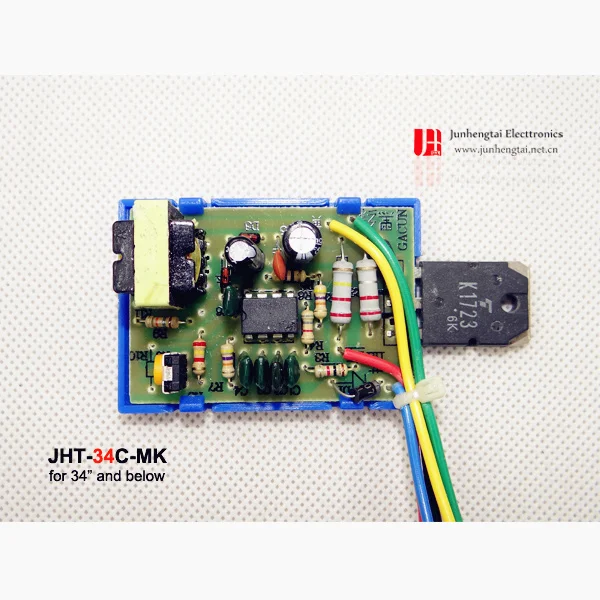
3 Wire For 34"crt Tv Switching Power Board Module Buy
Supply Top Sale 3 Wire 21" Crt Tv Power Module For Repair
Universal Ac Adapter Wiring Diagram Complete Wiring Schemas


DMO465R Universal Power Supply Module Installation In CRT

1wire relay/sensor, 2 channels ( DS2413P chip )
3wire For Repair Crt Color Tv Power Module Buy Crt Color

[Download 43+] China Universal Crt Tv Board Schematic Diagram
5 Cable 29" Power Module For Tv/dvd/ Vcd Buy Power
5wire For Repair Switching Power Supply Module For 29" Tv
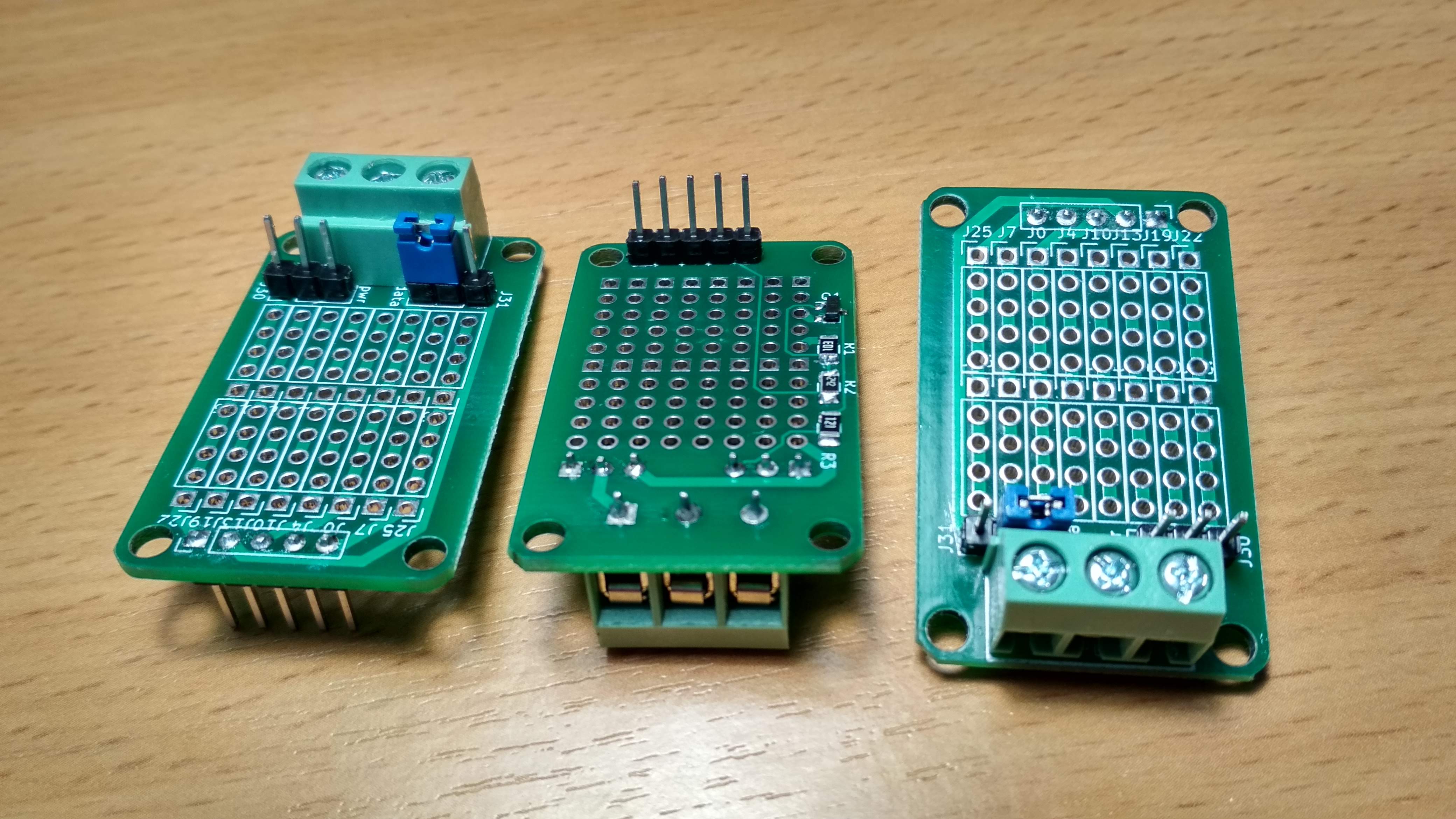
1wire relay/sensor, 2 channels ( DS2413P chip )
1wire relay/sensor, 2 channels ( DS2413P chip )

CA888 LCD Display Universal Power Supply Module EEE Shop BD

Universal Ac Adapter Wiring Diagram Complete Wiring Schemas
5 Wire CRT TV Power module, View 5 wire CRT TV power

China Universal Tv Board Schematic Diagram 15
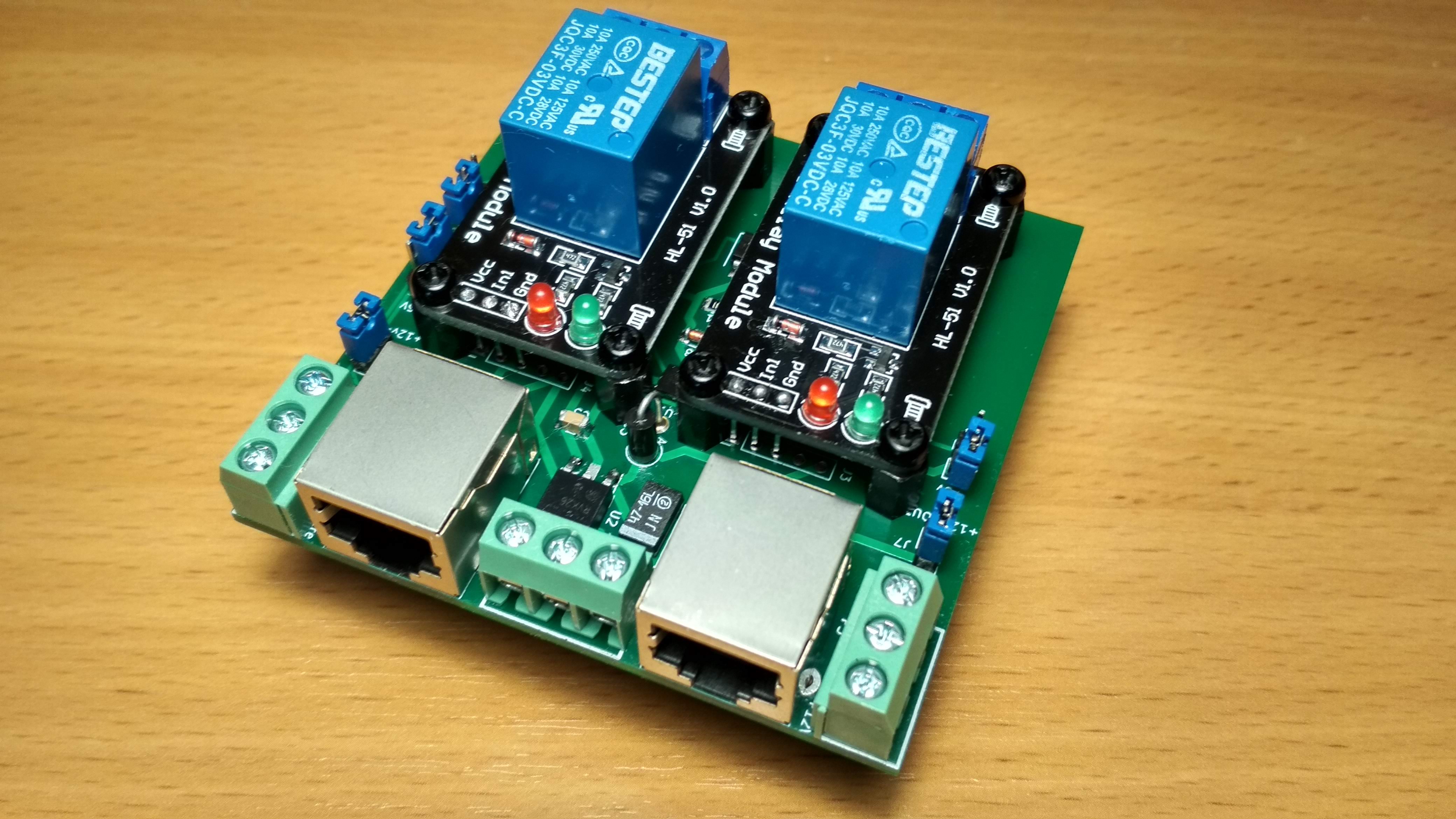
1wire relay/sensor, 2 channels ( DS2413P chip )
Klymk21c Tv Power Modulefor 21inch And Below 21 Inch Use


[DIAGRAM] Digital Power Supply Wiring Diagram Governor
3wire For Repair Crt Color Tv Power Module Buy Crt Color